

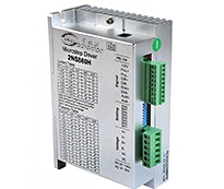
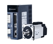
2NS556C

category:Digital stepper driver
- Brand:BERGERDA
- The number of clicks:
- Release date:2023/07/25
- specification:
- Types of:
- Online Inquiry
- Detailed introduction
Based on TI's new 32-bit multi-channel DSP processing chip platform, using internal PID current control algorithm design, with excellent performance. The built-in micro-segmentation technology and the automatic tuning function of the power-on parameter make the driver have the characteristics of low noise, low vibration, low heat and high-speed high-moment output, and can be well adapted to most applications of stepping motors.
Pulse mode: single pulse/ CW/CCW pulse/quadrature pulse
Signal level: 3.3-24V compatible, PLC applications without string resistance.
Typical applications: engraving machines, marking machines, cutting machines, laser equipment, plotters, CNC machine tools, automatic equipment equipment, etc. The application effect is particularly good in a device where the user desires high speed and small noise.
Drive function description
Drive function | Operating Instructions |
Microstep subdivision setting | SW5-SW8 four dial codes are used to select a total of 16 files of microsteps. When the user sets the subdivision, driver should be stopped first. For detailed microstep subdivision settings, please see the drive panel description. |
Output current setting | SW1-SW3 three dial switches are used to select a total of 8 output currents. For the specific output current setting, please see the driver panel description. |
Automatic half-flow function | Users can set the drive's automatic half-current function through SW4. Off indicates that the quiescent current is set to half of the operating current, and on indicates that the quiescent current is the same as the operating current. In general use, SW4 should be set to off, so that the heat generated by the motor and driver can be reduced and the reliability can be improved. The current is automatically halved approximately 0.4 seconds after the burst stops. |
Signal interface | PUL+ and PUL- are the positive and negative ends of the control pulse signal; DIR+ and DIR- are the positive and negative ends of the direction signal; ENA+ and ENA- are the positive and negative ends of the enable signal; |
Motor interface | A+ and A- are connected to the positive and negative terminals of the A-phase winding of the stepping motor; B+ and B- are connected to the positive and negative terminals of the B-phase winding of the stepping motor. When A, B two-phase windings are exchanged, the motor can be in the opposite direction. |
Power interface | Using DC power supply, R60 working voltage range is recommended 24-50VDC, voltage power greater than 150W. |
LED | The driver has two indicators, red and green. The green light is the power indicator. The green light flashes after the driver is powered on. The red light is the fault indicator. The red light flickers when there is a fault in the gear and the encoder is misaligned. After the fault is cleared, the red light goes out. When an alarm occurs on the drive, it must be powered on again to clear the fault. |
Installation Notes | Dimensions: 118 * 76 * 33mm, mounting hole spacing 112. Can be horizontal or vertical installation, but it should be close to the metal cabinet for better cooling |


URL of this article:https://en.bergerda.com/product/581.html
Key words:stepperdriver
Recently browse:
Related Products:
related news:
- Integrate Internet tools
- 2021 Guangzhou International Industrial Automation Exhibition
- 2023 Brazil exhibition
- 2021 Shenzhen Industrial Machinery Exhibition
- Guangdong industrial automation exhibition
- Internet plus represents a new economic form
- 2019 Mumbai Automation EXPO
- Special servo and stepping motor for mask machine
- Notice of identification of counterfeit bergdahl products
- Internet technology services
