

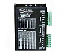
Closed loop stepper drive 2LS556

category:Closed loop stepper driver
- Brand:BERGERDA
- The number of clicks:
- Release date:2023/07/25
- specification:
- Types of:
- Online Inquiry
- Detailed introduction

Based on the platform of TI's new 32-bit multi-channel DSP processing chip, the magnetic field orientation and high-speed flux-weakening algorithm in the servo driver are designed to achieve excellent performance.
The built-in vector control design and servo demodulation function of the driver, combined with the feedback of the closed-loop motor encoder, make the stepping servo system have the features of low noise, low heating, no lost steps and higher application speed, and can improve the intelligent equipment system performance in all directions.
Pulse mode: single pulse/ CW/CCW pulse/quadrature pulse
Signal level: 3.3-24V compatible, PLC applications without string resistance.
Typical applications: lock screw machine, servo dispensing machine, stripping machine, labeling machine, medical detector, electronic assembly equipment, etc. The application effect is particularly good in a device where the user desires high rotation speed and high torque.
Drive function description
Drive function | Operating Instructions |
Microstep subdivision setting | SW1-SW4 four dial codes are used to select a total of 16 files of microsteps. When the user sets the subdivision, electric motion should be stopped first. For detailed microstep subdivision settings, please see the drive panel description. Other mirco step can be set through the debug software. |
Running direction setting | SW5 is used to select the initial direction of rotation of the motor. It is necessary to power off and restart the drive to make effect. |
Pulse smoothing selection | SW6 is used to select whether to enable the internal S-type command smoothing function. Turn on this function when ON to make the driver input pulse signal smoother. It is necessary to power off and restarts the drive to make effect. |
Pulse mode selection | SW7 is used to select the input pulse mode, off is the pulse & direction, and on is CW/CCW pulse. It can also be modified to quadrature pulses by the debug software. It is necessary to power off and restart the drive to make effect. |
Signal interface | PUL+ and PUL- are the positive and negative ends of the control pulse signal; DIR+ and DIR- are the positive and negative ends of the direction signal; ENA+ and ENA- are the positive and negative ends of the enable signal; ALM+ and ALM- are the Positive and negative ends of alarm output signals. |
Encoder interface | E8+ and E8- are encoder B direction signals; EA+ and EA- are encoder A direction signals; VCC and GND are encoder power interfaces.’ |
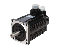
Motor interface | A+, A-, B+, B- are the stepping servo motor winding interfaces, which must be linked with the motor identification color and cannot be exchanged. |
Power interface | V+, V- are the positive and negative terminals of the input DC power supply, and the NC is empty. 2LS556 operating voltage range 24-50VDC, voltage power greater than 150W. |
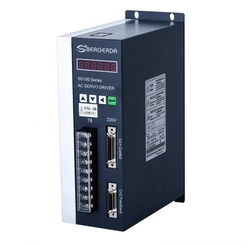
LED | The driver has two indicators, red and green. The green light is the power indicator. The green light flashes after the driver is powered on. The red light is the fault indicator. The red light flickers when there is a fault in the gear and the encoder is misaligned. After the fault is cleared, the red light goes out. When an alarm occurs on the drive, it must be powered on again to clear the fault. |
Installation Notes | Dimensions: 116 * 70 * 27mm, mounting hole spacing 109. Can be horizontal or vertical installation, but it should be close to the metal cabinet for better cooling |


LS series closed loop stepping introduction
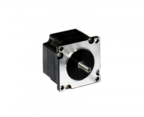
The closed-loop stepping drive of Bergerda is based on an ordinary open-loop stepping motor combined with position feedback and servo algorithm to form a high-speed, high-torque, high-precision, low-vibration, low-heat, No-lose-step stepping scheme. LS series stepping servo driver, based on the platform of IT company's new 32-bit DSP processing chip, utilizes magnetic field orientation (FOC) and weak magnetic control algorithm design in servo driver, and has all-round performance beyond ordinary stepping.
Built-in PID parameter adjustment function enables the motor to better meet the application of different types of loads.
Built-in field weakening control algorithm reduces the magnetic field characteristics of the motor at high speed and maintains power.
Built-in current vector control function makes the motor have servo current characteristics and low heat generation.
Built-in micro-step instruction algorithm, so that the motor speed stage to maintain stable, low vibration.
Built-in 4000pulse resolution encoder feedback, so that the motor accuracy, never lost step.
The servo control direction combined with the characteristics of the stepping motor enables the LS series closed-loop stepping driver to better perform the performance of the stepping motor and replace the same power servo application, making the automation equipment the most cost-effective new choice.
Application: It is especially good for users who want small noise and high speed equipment. For example: engraving machine, stripping machine, marking machine, cutting machine, solid crystal machine, plotter, CNC machine tools, automatic assembly equipment.
Drive function description
Drive function | Instructions |
Command pulse form | The standard LS series driver signal interface is in pulse form and can accept three types of pulse command signals; 1. Pulse & Direction (PUL + DIR); 2. Double Pulse (CW + CCW); 3. Quadrature Pulse (A/B Quadrature Pulse) |
Alarm Output | The alarm output port ALM is used to output the drive operation status to the external control circuit. When the driver is in the error state and normal operating state, ALM outputs different optocoupler levels. Alarm signals can be reused as in-position signals. |
Control algorithm is optional | The leading space vector servo control algorithm and the traditional advance angle control algorithm are optional, and the user can arbitrarily select according to the occasion. |
The highest pulse frequency is optional | With the highest pulse frequency of 200K and 1MHZ as standard, optional debugging software can modify any maximum pulse frequency within 1M. |
Wide voltage range on Signal terminal | The pulse, direction, and enable signal input interface voltages are 3.3 to 24V compatible, eliminating the need for a series limiting resistor. |
Seven status LED displays | The LS series driver has two operating states and five fault LED indication functions, allowing the user to clearly confirm the status of the driver. |

URL of this article:https://en.bergerda.com/product/585.html
Key words:steppermotor,stepperdriver
Recently browse:
Related Products:
related news:
- Special servo and stepping motor for mask machine
- Internet technology services
- Internet plus represents a new economic form
- 2021 Shenzhen Industrial Machinery Exhibition
- 2023 Brazil exhibition
- 2019 Mumbai Automation EXPO
- 2021 Guangzhou International Industrial Automation Exhibition
- Guangdong industrial automation exhibition
- Integrate Internet tools
- Notice of identification of counterfeit bergdahl products
