

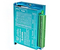
3NS2280

category:Digital stepper driver
- Brand:BERGERDA
- The number of clicks:
- Release date:2023/07/25
- specification:
- Types of:
- Online Inquiry
- Detailed introduction
Based on TI's new 32-bit DSP processing chip platform, the internal PID current control algorithm design, with excellent performance. The built-in micro-segmentation technology and the automatic tuning function of the power-on parameter make the driver have the characteristics of low noise, low vibration, low heat generation and high-speed high torque output. In addition, the patented three-phase demodulation algorithm can give full play to the low-speed resonance and small torque ripple characteristics of the phase stepping motor, and can be well adapted to applications requiring higher stability.
Pulse mode: single pulse/ CW/CCW pulse/quadrature pulse
Signal level: 3.3-24V compatible, PLC applications without string resistance.
Typical applications: potting machines, engraving machines, cutting machines, laser equipment, CNC machine tools, automatic equipment and so on. The application effect is particularly good in a device where the user desires high speed and small noise.
Drive function description
Drive function | Operating Instructions |
Microstep subdivision setting | SW5-SW8 four dial codes are used to select a total of 16 files of microsteps. When the user sets the mirco step, driver should be stopped first. For detailed microstep subdivision settings, please see the drive panel description. |
Output current setting | SW1-SW3 three dial switches are used to select a total of 16 output currents. For the specific output current setting, please see the driver panel description. |
Pulse smoothing and bandwidth selection | The SW9 dial code is used to select the pulse smoothing function of the driver. Off means turn this feature off, on means turn this feature on. SW0 is used to select the bandwidth of the driver. The maximum pass pulse frequency is 200KHZ when off, and the maximum pass pulse frequency is 1MHZ when on. |
Signal interface | PUL+ and PUL- are the positive and negative ends of the control pulse signal; DIR+ and DIR- are the positive and negative ends of the direction signal; ENA+ and ENA- are the positive and negative ends of the enable signal; ALM+ and ALM- are the positive and negative terminals of the alarm output signal; RDY+ and RDY- are the positive and negative terminals of the in-position signal. |
Motor interface | U, V, W butt the motor windings U, V, W, Arbitrarily swapping two of the three winding wires can change the direction of the motor., PE ground wire. |
Power interface | The working voltage range is recommended for AC 110-230V. It is recommended to add a filter (EMI FILTER) before the power supply circuit. |
LED | The driver has two indicators, red and green. The green light is the power indicator. The green light flashes after the driver is powered on. The red light is the fault indicator. The red light flickers when there is a fault in the gear and the encoder is misaligned. After the fault is cleared, the red light goes out. When an alarm occurs on the drive, it must be powered on again to clear the fault. |
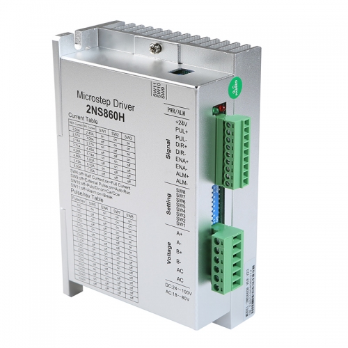
Installation Notes | Dimensions: 203 * 147 * 78mm, mounting hole spacing 193. Can be horizontal or vertical installation, but it should be close to the metal cabinet for better cooling |

URL of this article:https://en.bergerda.com/product/583.html
Key words:stepperdriver
Recently browse:
Related Products:
related news:
- 2021 Shenzhen Industrial Machinery Exhibition
- Guangdong industrial automation exhibition
- Notice of identification of counterfeit bergdahl products
- 2021 Guangzhou International Industrial Automation Exhibition
- 2019 Mumbai Automation EXPO
- Special servo and stepping motor for mask machine
- Internet plus represents a new economic form
- Integrate Internet tools
- Internet technology services
- 2023 Brazil exhibition
